
![[Raspberry Pi - Arduino ]Lamp Switch](http://hack.lenotta.com/wp-content/uploads/2013/10/IMG_3733skin1.png) [Raspberry Pi – Arduino ]Lamp Switch[/caption]
[Raspberry Pi – Arduino ]Lamp Switch[/caption]
A month ago we planned to manage our Arduino irrigator (aka Irrigatorino) through the NRF24l01+ wireless module. Our little project has been subjected to a little change, since we decided to make our life easier (buahahah…) and remote control a light over a browser (yes, mobile too). Surprisingly, a lot of people liked the little demo I’ve made with some raw code and asked for a tutorial, so here we are:
Ladies and (more probably) Gentleman, I’m glad to present you the lamp driven by a browser switch!
Nothing new actually, but still exciting!
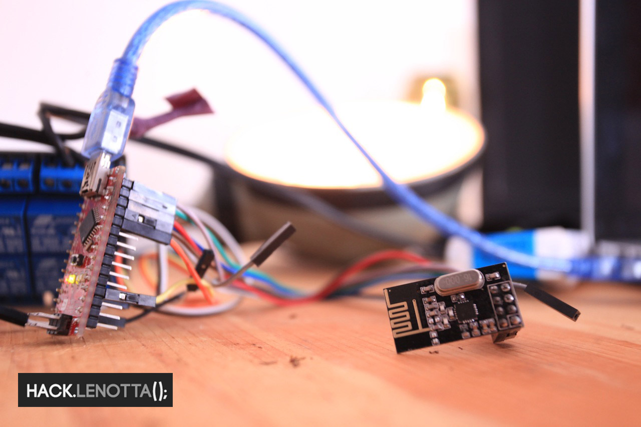
Arduino Nano 328 connected with NRF24l01+ module and Lamp (in the background)
Hardware:
To test the wiring we suggest you to use the ping/pong test you can find in the RF24 libraries (both, of the raspberry and the arduino).
Raspberry Pi
The connection between the Raspberry Pi and the NRF24l01+ module was a little bit tricky, so you have to double ( or triple) check the wiring before giving up. Here is the wiring scheme, the Raspberry Pi is a revision 2, and the module is the + (plus) version.

Raspberry Pi (rev2) – NRF24l01+ Diagram
Arduino
The setup is easy and similar to a mix of our tutorials about Irrigatorino and NRF24l01+ Tests.
Just keep in mind that you are playing with dangerous voltage, so if you get struck, it’s only your fault. I would suggest, anyway, to check if everything (especially the relay board) is working with a multimeter, before connecting to a real lamp.
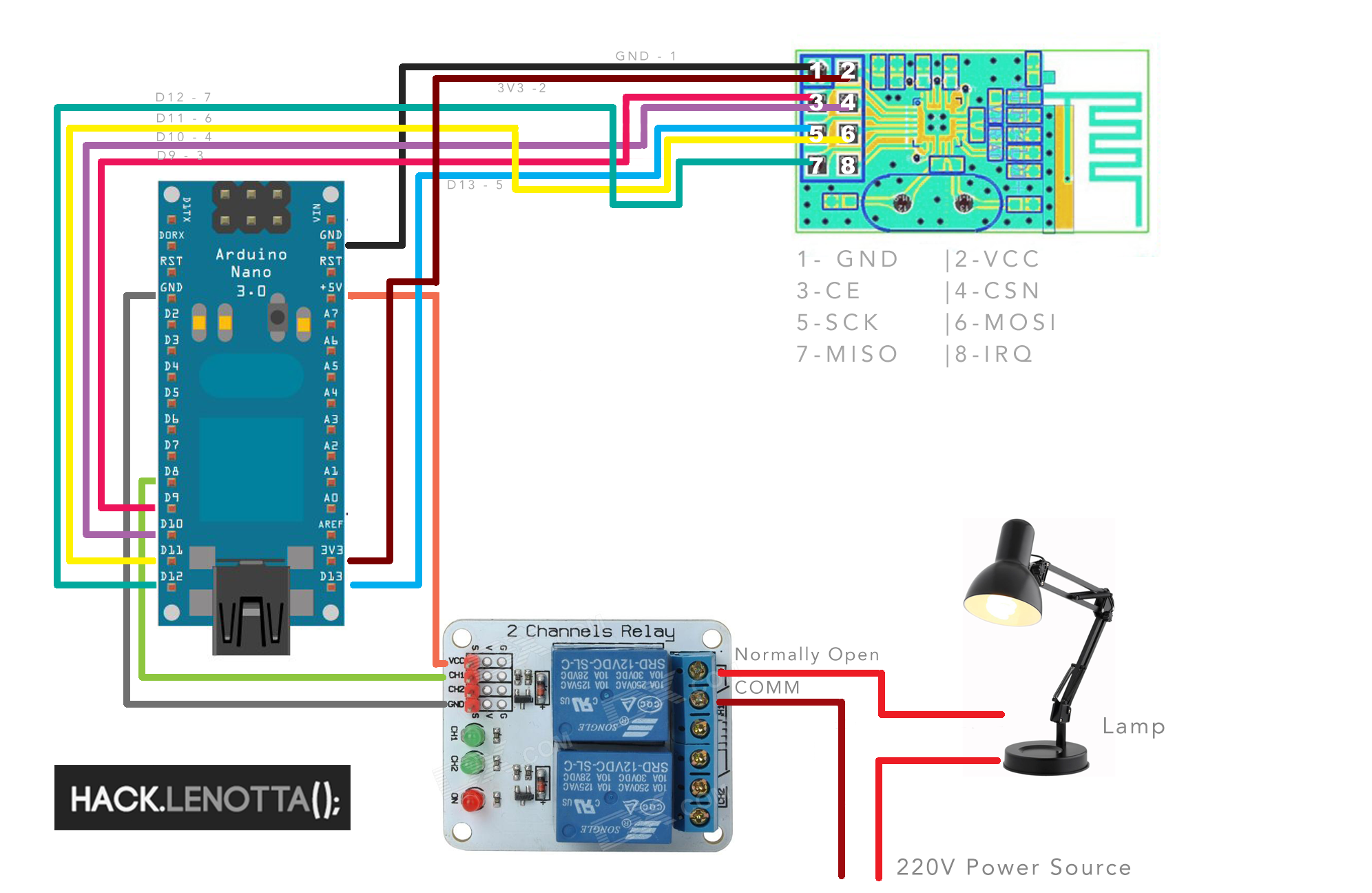
Arduino Nano – NRF24l01+ – Lamp Diagram
NOTE ON PACKET LOSS:
If you are encountering problems while receiving or transmitting, like packet loss, consider adding a capacitor of 10 μF between the pin 1 and 2 of the NRF24l01+, with ground capacitor side on pin 1. You should do this on both the modules, on raspberry and arduino.

Capacitor on NRF24l01+
Software
Our plan to communicate between all this stuff is to use a Node.js application to run a binary ‘sudo ./remote -m 81‘ and ‘sudo ./remote -m 80‘ sending a message to the Arduino with the text 81 and 80 . The message is composed by pin identifier (8) and action to perform (0|1|2). After the action has been read, all the other numbers identify the pin which the action refers to.
When the arduino receive it, it then sends back an acknowledgment packet to the raspberry with the same message (yeah, like a parrot), except for action 2, which will not perform any action, but will reply with actual state of the pin. In the meantime, if the message the arduino receive is 1 it will close a relay (turning on a light, like a good parrot), 0 will open it (I doubt a parrot could be so clever).
Sketching
The sketch for the Arduino Nano is nothing more than a Getting Started demo of the RF24 library. We just modified it to switch the relay on in case it receive a message with 1 as text, or open it otherwise. Of course you’ll need the RF24 library to make it work.
|
1 2 3 4 5 6 7 8 9 10 11 12 13 14 15 16 17 18 19 20 21 22 23 24 25 26 27 28 29 30 31 32 33 34 35 36 37 38 39 40 41 42 43 44 45 46 47 48 49 50 51 52 53 54 55 56 57 58 59 60 61 62 63 64 65 66 67 68 69 70 71 72 73 74 75 76 77 78 79 80 81 82 83 84 85 86 87 88 89 90 91 92 93 94 95 96 97 98 99 100 101 102 103 104 105 106 107 108 109 110 111 112 113 114 115 116 117 118 119 120 121 122 123 124 125 126 127 128 129 130 131 132 133 134 135 136 137 138 139 140 141 142 143 144 145 146 147 148 149 150 151 152 153 154 155 156 157 158 159 160 161 162 163 164 165 166 167 168 169 |
/* This program is free software; you can redistribute it and/or modify it under the terms of the GNU General Public License version 2 as published by the Free Software Foundation. */ /* Hack.lenotta.com Modified code of Getting Started RF24 Library It will switch a relay on if receive a message with text 1, turn it off otherwise. Edo */ #include <SPI.h> #include "nRF24L01.h" #include "RF24.h" #include "printf.h" int relay = 8; // // Hardware conf // // Set up nRF24L01 radio on SPI bus plus pins 9 & 10 RF24 radio(9,10); // // Topology // // Radio pipe addresses for the 2 nodes to communicate. const uint64_t pipes[2] = { 0xF0F0F0F0E1LL, 0xF0F0F0F0D2LL }; char * convertNumberIntoArray(unsigned short number, unsigned short length) { char * arr = (char *) malloc(length * sizeof(char)), * curr = arr; do { *curr++ = number % 10; number /= 10; } while (number != 0); return arr; } unsigned short getId(char * rawMessage, unsigned short length){ unsigned short i = 0; unsigned short id = 0; for( i=1; i< length; i++){ id += rawMessage[i]*pow( 10, i-1 ); } return id; } unsigned short getMessage( char * rawMessage){ unsigned short message = rawMessage[0]; return (unsigned short)message; } unsigned short getLength( unsigned int rudeMessage){ unsigned short length = (unsigned short)(log10((float)rudeMessage)) + 1; return length; } void setup(void) { // // Print preamble // Serial.begin(57600); pinMode(relay, OUTPUT); digitalWrite(relay, HIGH); printf_begin(); printf("\nRemote Switch Arduino\n\r"); // // Setup and configure rf radio // radio.begin(); // radio.setAutoAck(1); // Ensure autoACK is enabled radio.setRetries(15,15); radio.openWritingPipe(pipes[1]); radio.openReadingPipe(1,pipes[0]); radio.startListening(); radio.printDetails(); } int getState(unsigned short pin){ boolean state = digitalRead(pin); return state == true ? 0 : 1; } void doAction(unsigned short id, unsigned short action){ if( action == 0 ){ digitalWrite(id, HIGH); }else{ digitalWrite(id, LOW); } } void sendCallback(unsigned short callback){ // First, stop listening so we can talk radio.stopListening(); // Send the final one back. radio.write( &callback, sizeof(unsigned short) ); printf("Sent response.\n\r"); // Now, resume listening so we catch the next packets. radio.startListening(); } void performAction(unsigned short rawMessage){ unsigned short action, id, length, callback; char * castedMessage; length = getLength(rawMessage); castedMessage = convertNumberIntoArray(rawMessage, length); action = getMessage(castedMessage); id = getId(castedMessage, length); if (action == 0 || action ==1){ callback = action; doAction(id, action); }else if(action == 2){ callback = getState(id); } sendCallback(callback); } void loop(void) { // if there is data ready if ( radio.available() ) { // Dump the payloads until we've gotten everything unsigned short message; bool done; // char * new; unsigned short rawMessage; done = false; while ( radio.available() ) { // Fetch the payload, and see if this was the last one. radio.read( &rawMessage, sizeof(unsigned long) ); // Spew it printf("Got message %d...",rawMessage); performAction(rawMessage); delay(10); } } } |
Enabling Raspberry Pi GPIO and Installing Node.js
First we enable the Raspy GPIO:
|
1 2 3 4 5 6 7 8 9 10 11 12 13 14 15 16 17 18 19 20 21 22 |
sudo apt-get install python-dev #make sure to COMMENT the lines with spi-bcm2708 and i2c-bcm2708 modules sudo vim /etc/modprobe.d/raspi-blacklist.conf #be sure to have i2c-dev module in the /etc/module sudo vim /etc/modules sudo adduser pi i2c sudo apt-get update #reboot: sudo shutdown -r now #get the GPIO software wget https://pypi.python.org/packages/source/R/RPi.GPIO/RPi.GPIO-0.5.3a.tar.gz #untar it and install it tar -xzvf RPi.GPIO-0.5.3a.tar.gz cd RPi.GPIO-0.5.3a/ sudo python setup.py install sudo apt-get install i2c-tools |
Method 2 (not tested, but should work):
|
1 2 3 4 5 6 7 8 9 10 11 12 13 14 15 16 17 18 |
# #Pretty similar except for the python-dev package taken from the repos. #source: Adafruit.com sudo apt-get update sudo apt-get install python-dev sudo apt-get install python-rpi.gpio #add this two modules: i2c-bcm2708 i2c-dev sudo nano /etc/modules sudo apt-get install python-smbus sudo apt-get install i2c-tools # do COMMENT the lines with spi and i2c modules sudo nano /etc/modprobe.d/raspi-blacklist.conf |
Let’s install node.js.
If you don’t need the latest version you can install it from the repos:
|
1 |
sudo apt-get install nodejs |
Otherwise you can follow this instructions (under Ubuntu, Mint… section) to compile the latest version.
The Lamp Switch Application
For Raspberry Pi 2 users: some of our readers pointed out that this library is a bit outdated for the Raspberry 2 and it’s encountering some problems. Until we have time to update the article, please refer to this post on the Raspberry Official Forum to solve the “Preparing interface” stuck problem (kudos to Andrei).
What we need now is to write an application that will send a message to the arduino using the NRF24l01+ and the Raspi. So the first thing to do is download the RF24 library ported for Raspberry Pi. I would suggest to use git.
|
1 2 3 4 5 6 7 8 9 10 11 |
#install git sudo apt-get install git #move to home cd ~ #clone the RF24 repos from edoardoo's github fork git clone https://github.com/edoardoo/RF24RaspberryCommunicator.git #retrieve the RF24 libs cd ~/RF24RaspberryCommunicator/ git submodule init git submodule update |
Now let’s install the library:
|
1 2 3 |
#install the library cd ~/RF24RaspberryCommunicator/RF24 sudo make install |
At this point, with the RF24 library installed, you can use the compiled remote application or compile it yourself with make command:
|
1 2 3 4 5 6 7 8 9 10 11 12 13 14 |
cd ~/RF24RaspberryCommunicator #optional: compile the remote application: make clean && make # Use remote command to send message to arduino (use sudo!) # Message should be in this format: [id pin number][action to do] # We've set relay at pin 8 and actions are: # 0: turn off # 1: turn on # 2: get the actual state #this message will turn the light on: sudo ./remote -m 81 |
If everything went well you should be able to turn on (and off) the relay at this point using the sudo ./remote -m 81 application, hearing the famous ‘click’ from the relay board.
The Node.js Lamp Application
At this point the only thing left is to build a little node.js server and bind a click on a client browser to an exec function on the raspberry server.
Since it’s more than just a file, we’ve placed a link to the repository on github. All the code is commented, so I hope everything is clear.
We are using git submodule to add the base node application RemoteRaspberry. So here is a list of commands to clone the repo:
|
1 2 3 4 5 |
cd ~/RF24RaspberryCommunicator git clone https://github.com/edoardoo/LightSwitchInNode.git cd LightSwitchInNode/ git submodule init git submodule update |
Anyway, since we were a little bit confused on our first node application we’ve decided to write down a little note to help you understand:
– lightSwitch.js => is a link to the application (remote.js) you need to run with “sudo node lightSwitch.js” (the sudo is NEEDED). This is the web server and will launch the client interface too.
- views (folder) => contains the main layout and the basic template.
– routes.js => contains the route to the template.
- RemoteRaspberry (folder) => the basic node app, which contains:
-
package.json => required modules (with version) you need to run the application
-
node_modules (folder) => it’s an auto generated folder which contains the modules
-
public (folder) => contains remoteClient.js, the javascript code loaded on the client and bootstrap folder for styling
-
remote.js => the actual node app
To run the application you need to:
|
1 2 3 4 5 6 7 8 9 10 11 12 |
#install the dependencies cd ~/RF24RaspberryCommunicator/LightSwitchInNode/RemoteRaspberry #but first clean the npm cache sudo npm cache clean npm install #nom nom nom installing stuff #run the application cd ../ sudo node lightSwitch.js |
Authors note (31/3/2014)
We love the way you support each other in the comments! It’s really a satisfaction for us.
We can’t be always here to answer your questions or doubts, and all your contributions are a really great value you add to this website.
Thank you all!
Update (10/5/2014)
We’ve refined a bit the code, making it more clean and definitely more readable. All you have to do now to add new buttons, is to create a new button in the node app views giving it a data-command tag. The value of that tag will be automagically passed to the old switch -f binary (now called remote -m). Of course you still need to tell arduino how to interpret the message. No more c++ recompiling. Plus, we’ve made the web interface give you a visual feedback when the raspberry receive the ack package from arduino.
Update (27/8/2014)
Looks like the Rf24 library author has changed the folder’s name. I’ve tried to fix the article with the new names. Didn’t have time to check it yet. Let me know if everything is ok. Edo.
Update (2/12/2014)
I’ve cleaned and updated the code to the latest RF24 libraries from TMRh20. I’ve managed to submit a bug (issue #46)of the RF24 lib to the TMRh20 github account, and apply the workaround he proposed. Unfortunately it looks like the modules needs time between communications, it’s a known bug that right now we don’t have time to fix. If you would like to fork the RF24RaspberryCommunicator project, magically fix it and make a pull request, we would love it. Right now, since we do it for free, we don’t have time to fix it. Hope you like it. Edo.
Update (17/01/2016)
For the Raspberry Pi 2 users who got stucked at “Preparing interface” message, please refer tothis post on the Raspberry Official Forum .
Have Fun!


